Module 12 - Making System Architecture Changes
Introduction
This document outlines the procedure for making architecture changes to an installed OptaSense 6 system. One of the biggest advantages of the install scheduler is the ability to be able to stack tasks and have it work through them in the background. This means that the scheduler can be closed whilst it works its way through them, in most instances enabling the main software to be run.
Pre-Requisites
Please ensure the following are complete and available before work is started:
- The system is up and running, and OS version 6 is installed on the control unit (CU).
- The user is logged into the CU as Administrator.
- The system is complete, and System Health shows no issues or disconnected items.
- All instances of the OS6 software are stopped on any other CU.
- The System configuration (config) has been exported.
Launching the Install Scheduler
- Launch the Install Scheduler from the Windows start menu.
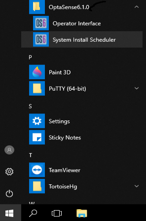
Figure 1: Launching Install Scheduler
- A notification appears informing the user that the application can be used to make architectural changes to the system. Click Yes to proceed.
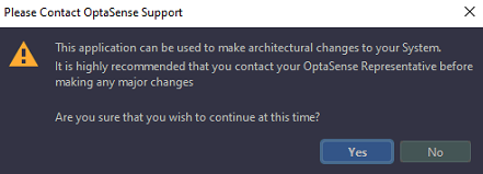
Figure 2: Confirm Making Changes to System Architecture
- Login with a user account who has ‘Super-user’ privileges
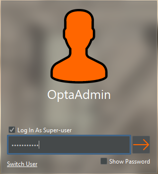
Figure 3: Log in to User Account
Pre-Install Checker
The purpose of the install checker is to see if the current system meets the minimum requirements to run OS6.
- Click on the + symbol and select preinstall checker.
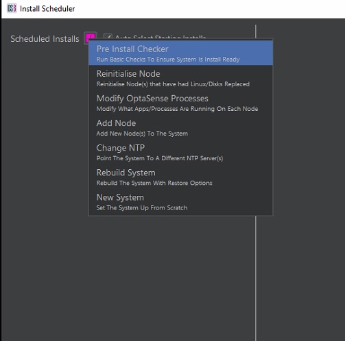
Figure 4: Selecting Pre-Install Checker
- This opens a task window. If the requirements are met, the task display’s as green and red it has failed.
Example of Passed & Failed Task
It’s important for the user to be aware of whether a task has passed or failed to process. Image 5 shows a task that has passed and has been implemented on the system.
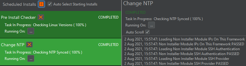
Figure 5: Task Passing & being implemented on the System
As can be seen in image 6, the task to has failed. Should this occur, an indication as to why it failed may be found in the process logs (right of failed task). Alternatively contact OptaSense for direction.
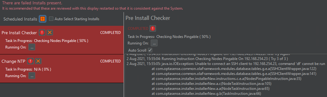
Figure 6: Task failing
Reinitialise PU(s)
The reinitialise PU feature enables the Operator to reintroduce a PU into the system after having its operating system hard disk replaced. Note, Linux would need to be installed on the replacement disk, using the same configuration details that the previous disk used. Pay attention to details like, the Linux version, ethernet port addressing, or whether the node was using a Mellanox network card.
- Click on the + symbol and select Reinitialise PU(s).
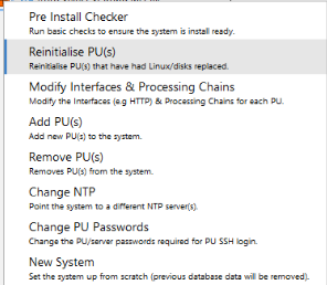
Figure 7: Selecting Reinitialise PU
- Tick the required PU(s) required for reinitialise and ‘Apply Changes’.
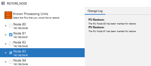
Figure 8: Marking PU(s) for Reinitialise
- Before the reinitialise starts, you must confirm that system has the correct password for the PUs which is about to be reinitialized. Normally the PU will have the default password (as it is assumed that PU has had a fresh Linux Install). Once confirmed, the task will run on the main window to reinitialise the PU(s).

Figure 9: Confirm Current PU Password
If the installer fails, seek OptaSense Support before taking any further action
Modify Interfaces & Processing Chains
To modify the processes running on each PU, select the ‘Modify Interfaces & Processing Chains’ menu option. With this option, Operators can add Interfaces like HTTP or modify the IU Processing Blocks running on each PU.
- Click on the + symbol and select Modify OptaSense Process.
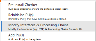
Figure 10: Selecting Modify Process
- Interfaces can be allocated by using the right-click menus on each PU.
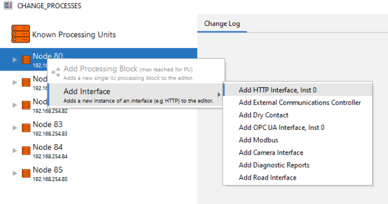
Figure 11: Adding HTTP to a PU
- Interfaces can be removed from PUs by right-clicking on the interface
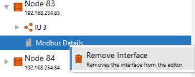
Figure 12: Removing Modbus from a PU
IU Processing Blocks can be added and removed in a similar fashion to Interfaces but changing processing blocks on a live System would not be considered normal operating behaviour.*
-
Once the required modifications have been applied to the editor, the Operator needs to ‘Apply Changes’
Note - Once finished, all Operator interfaces need to be restarted.
Adding New PU(s) To the System
To increase the size of the system, Operators can make use of the ‘Add PU’ feature. Operators must ensure these new PUs are contactable by the rest of the system while also ensuing the new PUs has the same Linux version as the rest of the system.
Before proceeding, it is advisable a backup of system alerts and the config is made.
- Click on the + symbol and select Add PU(s).
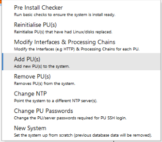
Figure 13: Selecting add PU(s)
-
Select the ‘Add Processing Unit’ option by right clicking on the ‘Known Processing Units’ label.
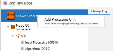
Figure 14: Selecting add Processing Unit
- Enter the required PU name, its IP address and select if the PU is DPU spec. Once entered, ‘Add PU’.
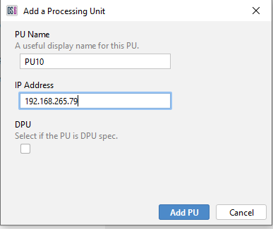
Figure 15: Entering new PU Credentials
-
At this stage, the Operator will get the choice to add the IU Processing Blocks (Input Processing, Algorithms, Rolling Recorders etc) for the new PU. In most cases, Operators would create the IU Processing Blocks. One case however where Operators would not be creating blocks is where the PU is not going to be connected to any IU and is acting as an additional Database Server.
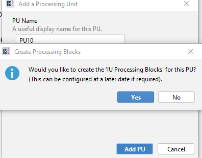
Figure 16 Choice to create IU Processing Blocks
-
The Operator will now need to create ‘IU Processing Blocks’ for the PU (if required).
-
An IU Processing Block consists of all the processing required for one IU.
-
If the PU is DPU spec, two blocks will be required (as there will be two IUs on that DPU).
-
The processes that sit under a single block include Input Processing, Algorithms, and the Rolling Recorders.
-
If the IU has the capability of monitoring 2 fibres simultaneously (e.g. OLA2.2), then the number of OPSs should be set to ‘2’.
When creating a Processing Block, Operators need to provide a useful block name (IU Serial number, Block Valve station name etc) and the starting OPS.
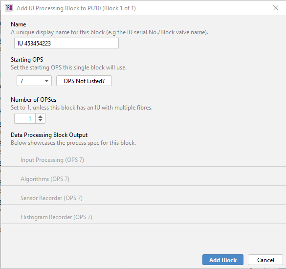
Figure 17: Creating a processing block
-
-
Once the IU Processing Block details have been added, the Operator should select ‘Add Block’.

Figure 18: New processing block in editor
-
Operators at this point can add Interfaces to the new PU if required. See ‘Modifying Interfaces’.
-
Once the Operator has added the required PUs and their processing, the Operator can ‘Apply Changes’ in which the editor will ask to confirm the password for the new PU(s).

Figure 19: Confirm PU Password
-
Once confirmed, the Installer will add the new PU(s) to the system.
Note – All Operator Interfaces need to be restarted after the new PU(s) have successfully been added. The system may also encounter consistency issues with alerts while scheduled repairs are waiting to be ran. Please seek OptaSense Support for more information about this matter.
If the installer fails, seek OptaSense Support before taking any further action.
Removing PU(s) From the System
To reduce the size of the system, Operators can make use of the ‘Remove PU(s)’ option.
Before proceeding, it is advisable a backup of system alerts and the config is made
- Click on the + symbol and select Remove PU(s).
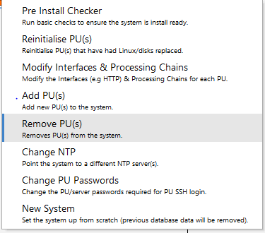
Figure 20: Selecting Remove PU option
- Tick the required PU(s) required for removal and ‘Apply Changes’.
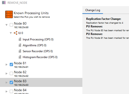
Figure 21: Selecting PUs for removal
- Before the removal starts, you must confirm that system has the correct password for the PUs about to be removed. Once confirmed, the task will run on the main window to remove the PU(s).
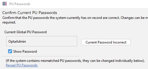
Figure 22: Confirm PU passwords
Note – All Operator Interfaces need to be restarted after the new PU(s) have successfully been removed. The system may also encounter consistency issues with alerts while scheduled repairs are waiting to be ran. Please seek OptaSense Support for more information about this matter.
If the installer fails, seek OptaSense Support before taking any further action.
Change System Wide PU Password
-
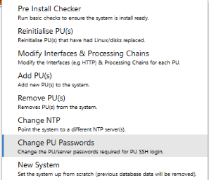
Click on the + symbol and select Change PU Passwords.
-
The Operator will be prompted to confirm that the current system wide PU password. If for any reason there are mismatched PU passwords, this display allows the current password to be inputted on a per PU basis. Click confirm to process to the next step.
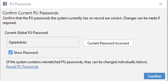
Figure 24: Confirm System Wide PU Password
- The Operator is then asked to enter the desired system wide PU password. Once confirmed the Software will proceed to update the PU passwords for all PUs.
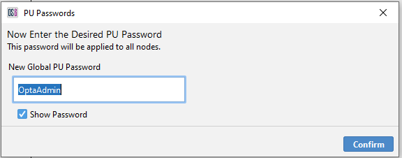
Figure 25: Enter Desired System Wide PU Password
Change NTP Source
The NTP source can be changed so that the system looks to another device for the system time. The alternative source must be handing out time in UTC format as failure to do so will results some of the features (map / detector settings) being unavailable in the main software.
- Click on the + symbol and select Change NTP.

Figure 26: Selecting Change NTP
- A box will appear allowing the user to edit the current IP address or add an additional source. The purpose of the additional sources is to provide redundancy should the primary fail. Having added the required devices, Click ok.
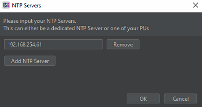
Figure 27: Entering New NTP Source Details
New System
The new system feature allows the user to take the existing system, import a configuration and effectively start the system from a fresh install. It’s important to note that using this method purges the previous system, wiping data like Alerts and latest configuration changes. Therefore, it’s strongly advised a backup config is made before proceeding.
- Click on the + symbol and select new system.
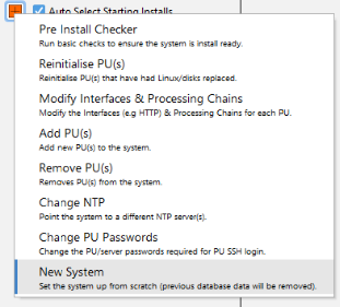
Figure 28: Selecting New System
- Select the required config and click open.
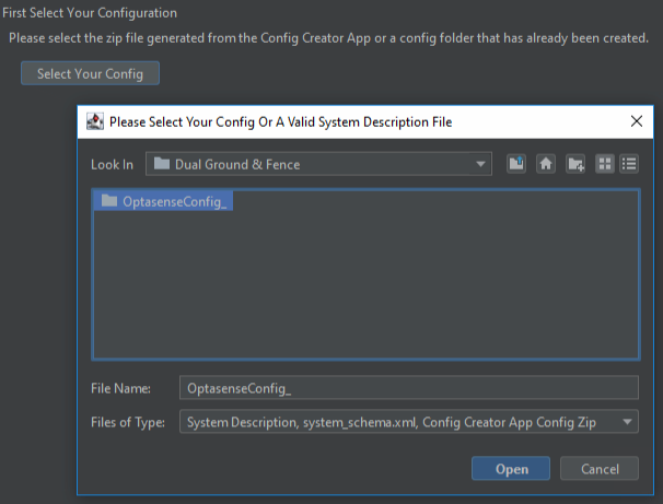
Figure 29: Importing Config of the New System
- Enter the NTP IP address of the time source the system is to use. It’s essential that the alternative source can service the time in UTC as failure to do so results in some of the OptaSense 6 features becoming unavailable. Once all details are entered click continue to proceed to the next steps.
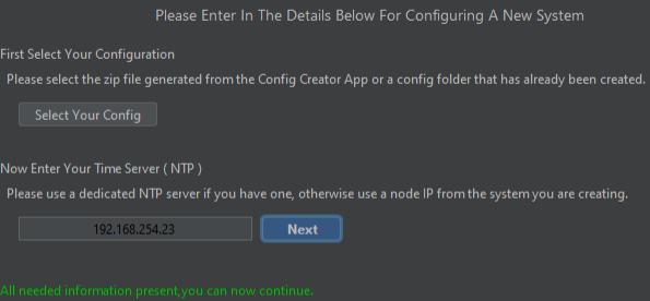
Figure 30: Entering NTP Source Details
- Before the new system task starts, the Operator will be asked to confirm that the current system wide node password. If there are mismatched node passwords, this display allows the current password to be inputted on a per node basis. Click confirm to proceed to the next step.
- The final step now asks for the desired system wide PU password. The operator can proceed without making any changes. Once confirmed, the new system task will run on the main display.
Figure 32: Enter Desired System Wide PU Password